
Marine Radar: The Complete Guide about Marine Radar
1:- What Radar Means
The marine radar is probably the most important bridge equipment and navigational aid onboard as it is crucial for collision avoidance and early detection. Marine Radar Technology was first properly used during World War 2 and since then, has undergone several advancements. In this Blog, we will discuss everything you need to know about the Marine Radar on ships and provide a comprehensive overview for future reference. So let’s begin
2:- Marine Radar Block Diagram
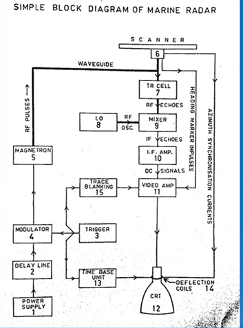
This is a simplified marine radar block diagram of the Marine Radar. However, it will serve as a founding stone of your understanding of the Marine Radar, so you need to carefully examine it.
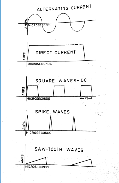
3:- Wave Forms Used in the Marine Radar:
4:- Working of Radar
The Marine Radar consists of four different components:
- The Transmitter
- The Aerial or Scanner
- The Receiver
- The Display
Let’s understand each unit in detail:
4.1:- The Transmitter in Marine Radar
The transmitter comprises the power supply, delay line, modulator, trigger, and magnetron. Pulses are triggered into the modulator and the magnetron converts the Input into a high-frequency oscillation. These high-frequency oscillations are fed by a waveguide or a coaxial cable into the transmitter-receiver switch.
4.2:- The Scanner in Marine Radar
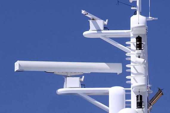
It sends the pulses out and receives the echoes, one direction at a time. The pulses are sent out at a pre-determined rate called the Pulse Repetition Frequency (PRF). It has a constant speed of rotation and hence the entire area around it gets scanned. It is usually located on Monkey Island clear of all obstructions.
4.3:- The Reciever in Marine Radar
The Reciever consists of the TR Cell or Transmitter-Reciever Switch, Local Oscillator, Mixer, I.F Amplifier, and Video Amplifier. The primary function of the receiver is to amplify the incoming weak echoes and make them suitable for transmission to the Indicator. The incoming signal is fed to a series of amplifiers and then further to a demodulator which smoothens out the signal.
4.4:- The Display of Marine Radar
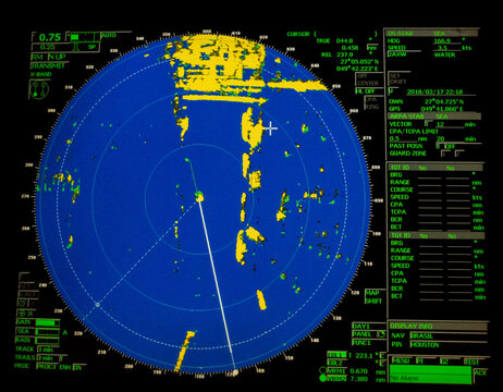
The display mainly consists of a Cathode Ray Tube (CRT) which provides a Bird’s Eye View and is called a Plan Position Indicator (PPI). A thin stream of electrons is made to strike the underside of the screen and move radially across from the center to the edge of the screen, at several times per second equal to the PRF. Thus one radial line (called the trace) is created for every pulse transmitted. The receiver processes each echo and causes it to show up visually as a bright spot on the screen of the display unit
5:- How are Range and Bearing Determined in the Marine Radar?
5.1:- How to Get Range Determination
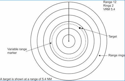
- To obtain the range of a target, range rings, and variable range markers are used.
- The tracing spot leaves the centre on its radial path at the same instant that the pulse leaves the scanner.
- The speed of the tracing spot is the scale speed equal to half that of the radio waves.
- By the time the pulse reaches the end of the trace, the radio waves will have traveled twice that distance If there is a target at one mile by the time the trace is completed one mile the echo will be back at the same spot and brightens the spot.
5.2:- How to get Bearing Determination
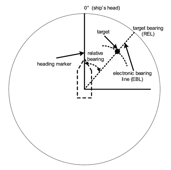
- The energy sent out by the scanner is made unidirectional (it is beamed in one direction (at a time).
- The scanner is made to rotate clockwise(when viewed from above) at a very constant speed (between 12 & 30 RPM).
- The trace on the screen is also made to rotate and is synchronized with the scanner.
- The PRF is so high (500 to 4000) compared to the RPM (12 to 30) that the angle rotated by the scanner between the transmission of a pulse and the arrival of the echo is negligible.
- So the paint of the target would appear in such a position on the PPI that the relative bearing of the target is the angle at the center, measured clockwise from the 12 o’clock position of the PPI to the paint.
- A stationary radial line, called the heading marker, extending from the center of the PPI to the zero of the bearing scale is constantly visible for reference.
6:- Types of Marine Radar Systems
Marine radars are categorized primarily based on their operating frequency and wavelength. Their use depends on their purpose, which is dependent on their characteristics. The two types of Radar used on ships are as follows:
6.1:- X-Band Radar (9Ghz / 3cm Radar)
They operate on a higher frequency range of 8-12 Ghz and have a shorter wavelength of about 2.5-3.75 cm. Marine X-Band Radars generally operate on 9 GHz and a wavelength of 3cm.
- Uses of the X-Band Radar:
- Due to a shorter wavelength, they provide a higher resolution picture in a shorter Range.
- As a result, it can differentiate better between smaller targets and clutter.
- They have smaller antennas and hence suitable for installation on smaller platforms.
- Limitations of the X-Band Radar:
- Their Shorter range makes them not suitable for Long Range Detection.
- In Bad Weather Conditions, X-Band Radars are more susceptible to attenuation due to rain, fog, or other atmospheric conditions.
6.2:- S-Band Radar (3 GHz / 10cm)
These Radar sets typically operate on a frequency of 2-4 Ghz and naturally, have a longer wavelength of about 7.5-15 cm, Marine S-Band Radars typically operate on a frequency of 3 GHz, having a wavelength of 10 cm.
- Uses of the S-Band Radar
- They have a longer range due to the longer wavelength and are suitable for long-range detection.
- In adverse weather conditions, the S-Band Radar is less affected and provides better imaging.
- Limitations of the S-Band Radar
- Lower Resolution Images compared to the X-Band Radar.
- The larger size of the Antenna can be a challenge however, it is tackled onboard during the design phase.
7:- SOLAS Requirements on Marine Radar
SOLAS Chapter V states the Carriage Requirements of Navigational Aids and includes requirements for the Radar as well.
They are as follows:
- All Ships over 300 GT, should carry:
- A 9 GHz Radar
- An Electronic Plotting Aid
- All Ships over 3000 GT, should carry:
- An Additional 3 GHz Radar
- An ARPA (Automatic Radar Plotting Aid)
8:- IMO Marine Radar Performance Standards
1974 SOLAS Convention mandates specific standards for all radar installations used onboard. RESOLUTION MSC.192(79) adopted on the 6th of December, 2004 specified the performance standards. Here are some of the most important ones:
- Bearing and Range Accuracy:
- Range – within 30 m or 1% of the range scale in use, whichever is greater;
- Bearing – within 1°.
- Bearing and Range Discrimination:
- The radar system should be capable of displaying two-point targets on the same bearing, separated by 40 m in range, as two distinct objects.
- The radar system should be capable of displaying two point targets at the same range, separated by 2.5° in bearing, as two distinct objects.
- The target detection performance of the equipment should not be substantially impaired when own ship is rolling or pitching up to +/-10°.
- An indication should be provided, in the absence of targets, to ensure that the system is operating at the optimum performance.
- The radar equipment should be fully operational (RUN status) within 4 minutes after switching ON from cold. A STANDBY condition should be provided, in which there is no operational radar transmission. The radar should be fully operational within 5 sec from the standby condition.
- Range scales of 0.25, 0.5, 0.75, 1.5, 3, 6, 12 and 24 NM should be provided. Additional range scales are permitted outside the mandatory set.
- At least two variable range markers (VRMs) should be provided. Each active VRM should have a numerical readout and have a resolution compatible with the range scale in use.
- The bearing scale should be outside of the operational display area. It should be numbered at least every 30° division and have division marks of at least 5°.
- Failure of any signal or sensor in use, including; gyro, log, azimuth, video, sync, and heading marker should be alarmed.
- A minimum of four independent parallel index lines, with a means to truncate and switch off individual lines, should be provided.
Disclaimer :- The opinions expressed in this article belong solely to the author and may not necessarily reflect those of Merchant Navy Decoded. We cannot guarantee the accuracy of the information provided and disclaim any responsibility for it. Data and visuals used are sourced from publicly available information and may not be authenticated by any regulatory body. Reviews and comments appearing on our blogs represent the opinions of individuals and do not necessarily reflect the views of Merchant Navy Decoded. We are not responsible for any loss or damage resulting from reliance on these reviews or comments.
Reproduction, copying, sharing, or use of the article or images in any form is strictly prohibited without prior permission from both the author and Merchant Navy Decoded.

Hi sir